


Have a question about the RANGER, or need help fixing a problem? Try searching here first, your issue may already be solved. If you’re not able to find your answer, please contact our tech support at +1 978-212-2868 x2, submit your question using the web chat, or fill out the contact us form.
Cloud
- Go to https://signal-fire.com/lte-m1-cellular-products/cloudregister/
- Enter your credentials and submit
- You will receive an email confirming a SignalFire Cloud account was created for your company.
*note: If your company already has an account, ask your SignalFire Cloud administrator to create a user for your login.
Any account with “User Admin” permissions can add additional users, by clicking the “Add User” button in the Users window. Be sure to assign the new user the appropriate user permissions
There is no limit for users per account
- User Admins can add, remove, or edit user profiles.
- Device Admins can configure the settings on a RANGER, and can control its digital output
- Alarm Admins can configure the alarm settings for a RANGER
- Alarm Ack allows a user to acknowledge active alarms
- Report Admins can configure automated reports
The data is stored for 3 years. The latest information will replace the oldest data after 3 years
The RANGER will store the last 200 events that have changed since the connection dropped, and then send that data to the cloud when the connection is restored
The RANGER uses the Sparkplug B MQTT format. Tag guides that detail all data tags from the RANGER can be found in the download tab for the RANGER on the signal-fire.com website
From the Node Status Tile, select “Hide/Show Tiles”. From this view unused tiles can be hidden from view. These changes will apply for all users within your group.
The RANGER can be configured to report immediately on change for its digital inputs. The Analog, HART, Modbus, SDI-12 inputs are only sampled at the configured reporting interval. The Fast Reporting feature can be configured to start reporting at a faster interval if an input crosses a threshold, or can report all inputs on the change of a DI trigger
Email: support@signal-fire.com or call us at (978)-212-2868 x2 to request a password reset
Yes it is possible to limit a user to where they can make no changes to the Cloud or RANGER settings by editing the user’s role. Removing their “Device Admin” permission will restrict them from changing the settings on any RANGERS, and removing their “Alarm Admin” is required to prevent them from making changes to the alarm configurations
You can customize the columns from the Home Screen.
- Click Configure on the top right of the Home page
- Use the drop downs for each row to select content for that column
- If using Modbus Registers, use the Button “Show Dynamic Values” and choose a Modbus Register. Once selected, the Drop Down selector will include “Custom [Modbus Tag]
Yes. If you select a RANGER, from the Node Status tile select Configure Node. From this screen you can “release” the RANGER from the group and it can then be claimed by another user group
You can view the expiration date on the Cloud through two ways:
- On the Home Screen, you can have a column that shows the Expiration Date
- On a given RANGER node, locate the “Node Status” Tile. There, you’ll find the expiration date
Furthermore, an email will be sent to the billing contact 60 days prior to expiration.
The SignalFire Cloud will keep collecting data for up to 30 days, but the live view will show data up to the point of expiration. After 30 days past expiration, the SIM card will become inactive and the RANGER will stop collecting data.
The RANGER supports TLS 1.2 with full validation to ensure a secure connection between the RANGER and the MQTT broker. Customers using their own MQTT broker have the option to load their own TLS certificates into the RANGER in addition to the factory certificates which are used to connect to the SignalFire Cloud
There is no limit for users per account
The fastest reporting interval is once every minute
No, each user account only supports one phone number. To add another phone number, you need to create another user
From the SignalFire Cloud, click the Modify button in the row containing the Modbus register to write. In the pop-up configuration window, enter the new register value and click the Set button. Note that the Register must be configured as a read/write register.
Networks
- Connect the RANGER ToolKit to the Ranger.
- Click on the Tools Menu and select Options.
- Select the “Show MQTT” Tab to expose the MQTT settings in the main RANGER configuration window.
- Under MQTT tab, click on Custom and enter the credentials for your MQTT Broker.
- Apply the changes, the RANGER’s modem will reboot. Look under MQTT Status on the main screen to confirm that the broker connected successfully
The RANGER’s modem supports both LTE-M Cat1 and NB-IoT cellular standards. The bands are specific to each carrier. Compare the available bands on the RANGER with the one from your cellular carrier. Currently, the RANGER is certified with Verizon, AT&T and has been connected to other networks like Rogers, TELUS, Bell, O2, Vodafone, Orange. SignalFire currently provides bundled data services through Verizon
The RANGER requires a 4FF size (nano) SIM. The SIM card and data plan much be capable of supporting LTE-M or NB-IoT networks. This is different than a standard 4G data SIM
No further configuration is necessary unless the carrier requires a user configured APN
No, the RANGER requires a IoT data plan specific to LTE-M or NB-IoT service
Many cellular carriers automatically configure the APN from the network side so the user is not required to set the APN manually. Verizon and AT&T automatically configure the APN. Other carriers may require the user to manually configure the APN, in which case the carrier will provide the required APN settings
- Connect the RANGER ToolKit to the Ranger.
- Click on the Tools Menu and select Options.
- Select the “Show MQTT” Tab to expose the MQTT settings in the main RANGER configuration window.
- Under MQTT tab, click on Custom and enter the credentials for your MQTT Broker.
- Click on Manage TLS Certificates and import your set of certificates into the RANGER
- Apply the changes, the RANGER’s modem will reboot. Look under MQTT Status on the main screen to confirm that the broker connected successfully
The RANGER needs a clear view of the sky for the GPS to obtain a position, and is unlikely to get a position fix indoors.
In the USA, you can use https://www.cellmapper.net/map to locate cell towers and coverage. We also recommend using the website of the carrier.
The RANGER does not have any open TCP ports or a public IP address so it not accessible over the internet. The RANGER initiates a secure connection to a MQTT broker and all data must pass through the broker
The RANGER does not have a public IP address, so this is not configurable
Both LTE-M and NB-IoT were developed by the 3GPP to address the growing need for wireless IoT (Internet of Things) devices, which need to consume as little power as possible, operate in remote areas, and are typically only sending a few bytes at a time.
LTE CAT-M1 (abbreviated LTE-M) is based on the existing cellular LTE framework your mobile phone uses, modified to serve low power IoT applications. For this reason, LTE-M is the dominant wireless IoT platform used in countries that have widely available existing LTE networks such as the U.S., Brazil, and Germany.
NB-IoT (Narrow Band IoT) is based on older GSM and CDMA technology and attempts to use large open sections on those spectrums. NB-IoT is being rolled out in countries that don’t have much LTE coverage and where GSM and CDMA are still popular, such as India, China, and South Africa.
Product
The RANGER is certified as follows:
- Hazardous locations: Non-Incendive – For use in Class I, Division 2, Groups A, B, C, D. Certified per UL 121201:2017 Ed.9+R:26Aug2019 and CSA C22.2#213:2017 Ed.3+U1;U2
- European health, safety, and environmental protection: CE, IEC62368-1:2014 2nd Ed, EN 62368-1:2014+A11:2017
- Cellular: PTCRB, Verizon LTE-Cat M1, AT&T LTE-CAT M1
Please visit: https://www.nordicsemi.com/Products/Low-power-cellular-IoT/nRF9160-Certifications to locate your country
The RANGER does not have an official enclosure rating, but is rated for outdoor environments and most closely follows NEMA/IP 3
The RANGER900 combines a SignalFire 900MHz gateway and the RANGER circuitry into a single enclosure along with a battery and solar panel. The allows users to easily bring data from SignalFire 900MHz devices to the SignalFire Cloud
No, the RANGER is not rated to applications where it may become submerged
The RANGER900 combines a SignalFire 900MHz Gateway with the RANGER. You can also connect the SignalFire’s Gateway Stick or DIN Gateway to the RANGER’S Modbus input. This requires the Modbus option with the RANGER. The number of registers is limited to 32 datapoints from up to 8 slave devices.
The standard ranges available are 0-2PSI, 0-20PSI, 0-100PSI, 0-500PSI, 0-1000PSI, 0-3000PSI, 0-5000PSI, 0-10000PSI, 0-15000PSI, and 0-20000PSI.
10,000PSI and below are available with a 1/2″ NPT fitting, 15,000PSI is available with a 1/2″ NPT or F250C Autoclave fitting, and 20,000PSI is available with a F250C Autoclave fitting. 10,000PSI and below are made with 316 Stainless Steel, while 15,000PSI and 20,000PSI are made with 17-4 PH
The RANGER can be powered by an internal 4D Lithium Thionyl Chloride high capacity battery pack (the default option), the SignalFire High Capacity solar system, or from an existing DC power source with the DC-DC converter option. The DC-DC’s input range is 9-36VDC
Toolkit
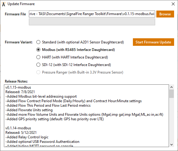
Firmware can be updated over the USB port using the RANGER ToolKit under Tools –> Update Firmware. Make sure to select the correct firmware file for your expansion card Over-The-Air firmware updates are also supported, but must be initiated by SignalFire at this time
- Wire the sensor to the RANGER’s HART card. Make sure to remove the jumper if the sensor is being externally powered
- Connect to the RANGER with the RANGER ToolKit
- Go to the HART tab
- Click on “Configure HART device”
- If the RANGER is set up for Sensor Always On or the sensor is externally powered, click Scan
- Otherwise, turn on power to the loop and wait for the sensors to turn on, then click Scan
- The connected sensors will appear at their configured HART ID
- Close out of the window and then check off which HART IDs you would like the RANGER to read and send to the Cloud
- Launch the RANGER Toolkit
- Click on the Tools Menu and select Battery Life Calculator
- Fill in the various inputs based on your application and expected usage
You may be trying to connect to an older unit. Check off “Show All” and click Refresh. You may also have a “charge only” cable.
Some micro-USB cables are “charge only” and do not contain the data lines required to communicate with the RANGER. Each RANGER ships with a micro-USB cable included. If the computer doesn’t create a COM Port when plugging in the RANGER to the computer, this means that the USB Cable doesn’t have communication capabilities
Hardware
The base RANGER has 2 digital inputs, 1 analog (4-20mA/1-5V) input, and 1 digital relay (SPDT) output. The analog input can power sensors with either 13V or 18V selectable in software. The RANGER also has an expansion slot to add more I/O.
Yes, the RANGER has an expansion slot to add more I/O with a daughter card. Available cards are 2AI1DI (2 analog, 1 digital), HART, RS485 Modbus, and SDI-12.
- With the RANGER powered off install the expansion card on the radio and secure with the supplied nut.
- The A2D1 card can be enabled from the Settings menu under “Select Daughter Card”
- The HART, Modbus and SDI-12 cards require that the corresponding firmware is loaded onto the RANGER.
- From the RANGER ToolKit, select Update Firmware from the Tools menu and select the latest firmware variant that corresponds to the installed card. For example, to enable the HART card on a v0.1.15 RANGER, upload firmware v0.1.15-modbus.
- Connect the RANGER ToolKit to the RANGER.
- Click on I/O tab
- Set the attached transmitter (or other mA source) to 4mA and click “Set Low Value”
- Set the attached transmitter (or other mA source) to 20mA and click “Set High Value/Calibrate”
The relay is a latching type and is rated 2A @ 30VDC; 0.3A @ 110VAC; 0.5A @ 125VAC
Any of the RANGER’S digital inputs can be configured for flow mode using the RANGER ToolKit or the SignalFire Cloud. When configured for flow mode additional settings are available to configure the pulse input K-Factor, flow rate and volume units. The analog inputs can also be configured to view instantaneous flow rate.
An external antenna can be useful in applications whenever the signal is -110dbm or less or when the connection drops out frequently (many times/day). Using an external antenna also allows for a directional antenna, which can greatly improve signal strength when pointed at the nearest cell tower.
The Sensor On Time can be set to 0 for externally powered sensors, and as low as 0.001 seconds (1ms) when the RANGER is powering the attached sensor(s)
The digital inputs continually count and totalize input pulses between reports
120 seconds, or Sensor Always On
This depends on the connected sensor(s), sensor-on time and reporting interval. The RANGER ToolKit will provide the average current draw for a specific configuration. The days of operation with no sun on a fully charged battery can be calculated using the following formula: Days = 6300 / (24 * average current)
No, the Pressure RANGER only supports its built-in pressure sensor. For applications that need measurement points in addition to pressure we recommend using an external 1-5V pressure transducer
The RANGER has an internal 470k pull-up resistor to 3.3V and typically does not require any external resistors when connected to meters with open collector, pulse or dry-contact outputs
The cellular signal will be weaker when not out in the open, so if the location is in a poor coverage area to begin with it may not work. An external antenna is recommended in these situations